KEJING Laboratory
科晶實(shí)驗(yàn)室
| (1) |
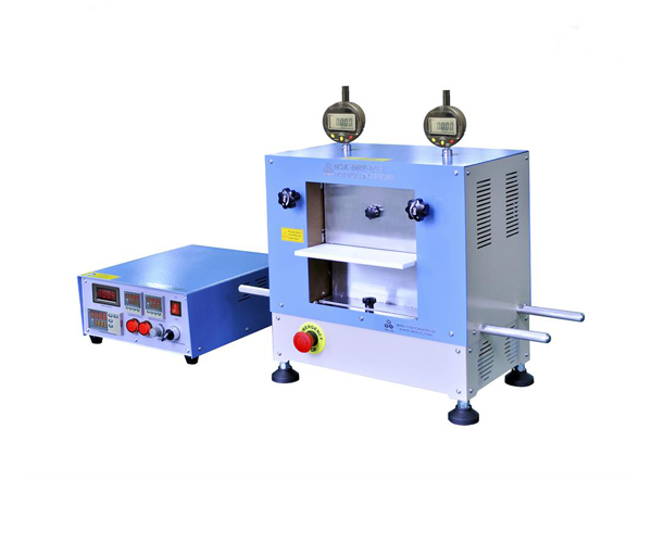
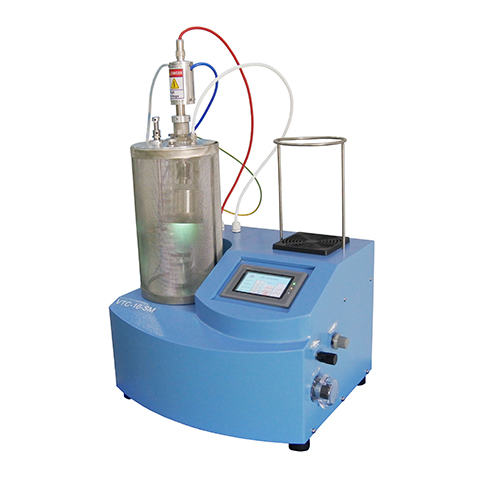
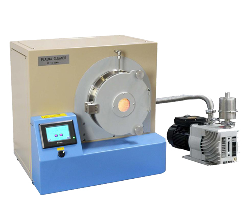
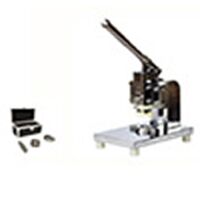
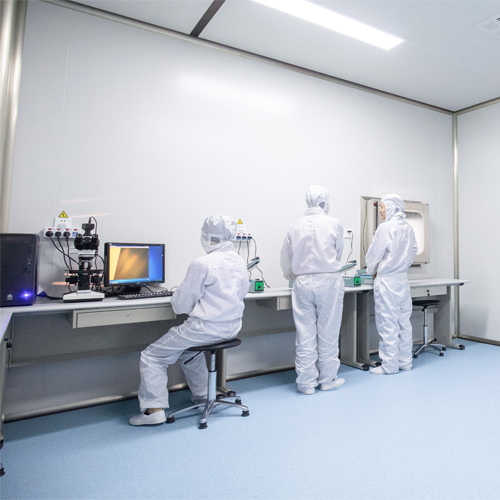
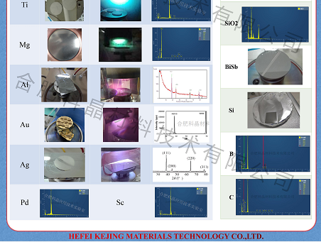
圍繞薄膜生長(zhǎng)設(shè)備的全套方案: 流延涂層,等離子濺射儀,旋轉(zhuǎn)涂層,提拉涂層,等離子清洗機(jī),滑動(dòng)快速等 |
| (2) |
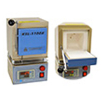
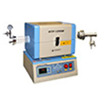
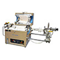
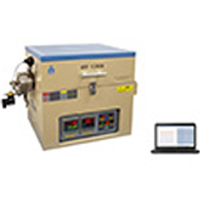
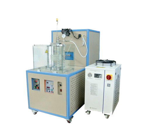
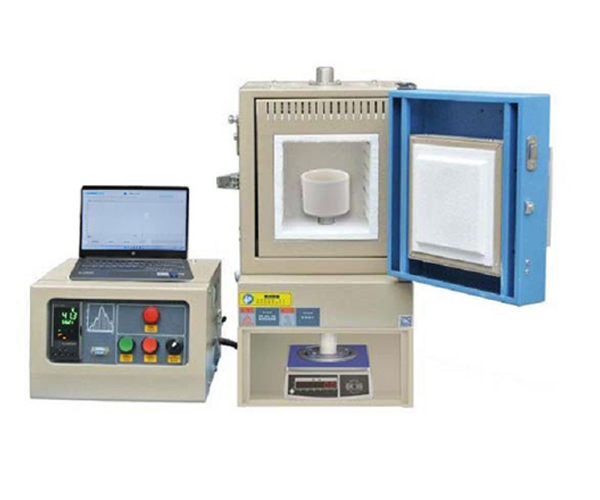
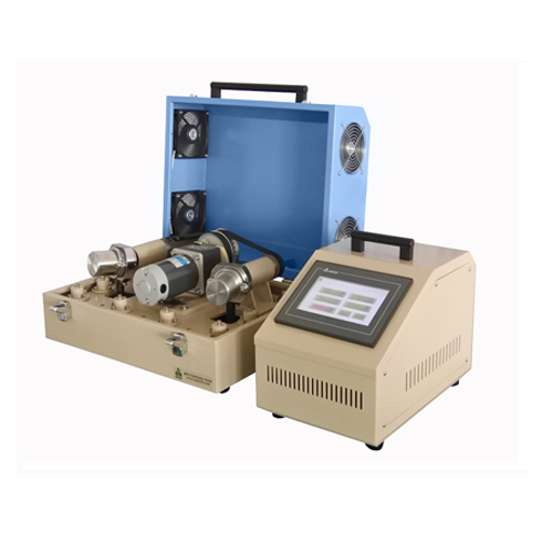
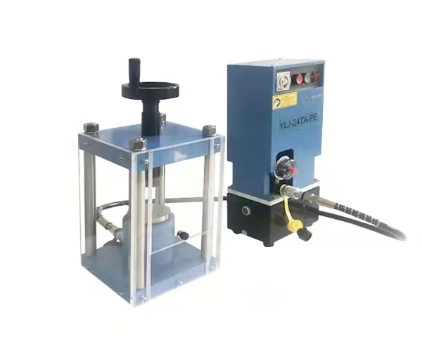
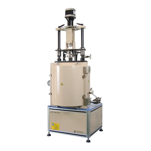
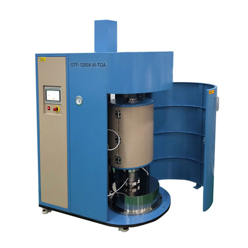
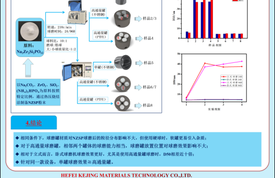
圍繞材料成相、燒結(jié),退火方案: 各種混料球磨機(jī),壓力機(jī)及熱壓機(jī),各式精密程控箱式爐,管式爐,高溫烘箱 |
| (3) |
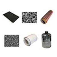
圍繞材料加工方案: 外圓切割機(jī),線切割機(jī),劃片切割機(jī),自動(dòng)拋光機(jī),壓力研磨拋光機(jī) |
| (4) |
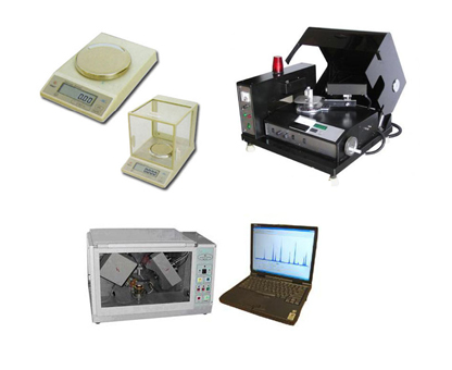
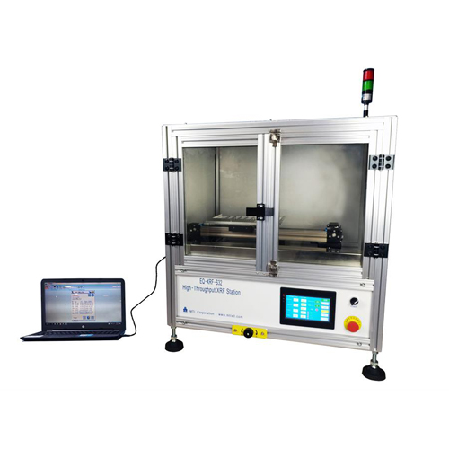
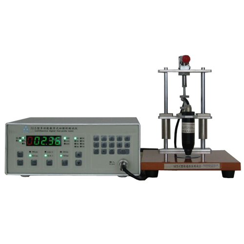
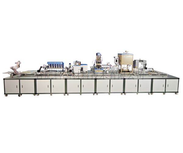
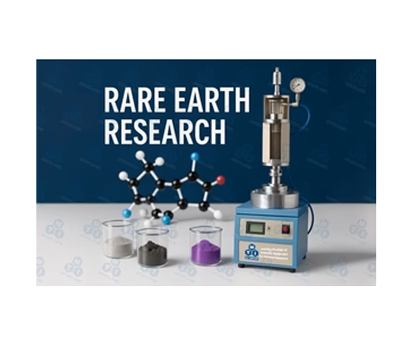
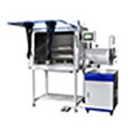
圍繞新能源材料研究方案: 混料機(jī),高溫爐,涂覆機(jī),軋機(jī),切片機(jī),封裝機(jī),以及檢測(cè)裝置 |
一張圖解決一個(gè)問(wèn)題系列
1、一張圖系列說(shuō)明 2、合肥科晶聯(lián)系方式 3、科晶加熱爐使用注意事項(xiàng) 4、科晶箱式爐使用說(shuō)明
實(shí)驗(yàn)室小課堂
1、如何根據(jù)應(yīng)用選擇科晶設(shè)備 2、假期后回到實(shí)驗(yàn)室不容忽視的N件事 3、放假前請(qǐng)做好實(shí)驗(yàn)室及儀器維護(hù) 4、浸漬提拉涂膜機(jī)的工作原理及分類
實(shí)驗(yàn)室安全1分鐘
1、實(shí)驗(yàn)安全(6):反應(yīng)釜的使用注意事項(xiàng)(二) 2、實(shí)驗(yàn)安全(5):反應(yīng)釜的使用注意事項(xiàng)(一) 3、實(shí)驗(yàn)安全(4): 灰化燃燒爐尾氣處理提示 4、實(shí)驗(yàn)安全(3):通風(fēng)柜的必要性
知識(shí)中心
1、知識(shí)中心模塊說(shuō)明 2、加熱爐 3、薄膜 4、晶體生長(zhǎng)
合肥科晶專利證書(shū)
| (1) |
免費(fèi)上門對(duì)科晶設(shè)備的使用進(jìn)行培訓(xùn)和工藝指導(dǎo)交流。: 適用:新接觸設(shè)備的科晶學(xué)生客戶。 |
| (2) |
免費(fèi)上門對(duì)設(shè)備進(jìn)行預(yù)防性維護(hù),減少設(shè)備故障概率。: 適用:設(shè)備數(shù)目型號(hào)較多,但是小故障較多,適用經(jīng)驗(yàn)不足的實(shí)驗(yàn)室或課題 |
| (3) |
在科晶實(shí)驗(yàn)室進(jìn)行設(shè)備體驗(yàn)性實(shí)驗(yàn)。: 適用:準(zhǔn)備購(gòu)買產(chǎn)品但是對(duì)產(chǎn)品不了解的客戶。 |
| (4) |
在科晶實(shí)驗(yàn)室進(jìn)行工藝摸索合作實(shí)驗(yàn)。: 適用:需要購(gòu)買較多設(shè)備,但是對(duì)工藝不了解,需要摸索的客戶。 |
| (5) |
遠(yuǎn)程長(zhǎng)期技術(shù)支持。: 適用對(duì)象:經(jīng)常碰到設(shè)備應(yīng)用小問(wèn)題,但又找不到人問(wèn)的科晶客戶。 |
Copyright © 2019 合肥科晶材料技術(shù)有限公司 版權(quán)所有 皖I(lǐng)CP備09007391號(hào)-1  皖公網(wǎng)安備 34012302000974號(hào)


 查看誠(chéng)信檔案